|
|
|
Schematics |
| |
| Supply for motor v. 1 Protection of the motor with a magneto-thermical circuit breaker + contactor |
| Supply for motor v. 2 Protection of the motor with fuse aM + contactor equiped with a thermal relay + load-switch for isolating |
| Supply for motor v. 3 Protection of the motor with a magnetical circuit breaker + contactor equiped with a thermal relay |
Supply for motor v. 4 Protection of the motor with a magneto-thermical circuit breaker + contactor |
| Supply for motor v. 5 Protection of the motor with a magneto-thermical circuit breaker + 2 contactors interlocked mechanicaly for inverting the rotating sens of the motor |
| Star-Delta starting circuitry Protection of the motor with a magnetical circuit breaker + contactor equiped with a thermal relay |
| Normal-Emergency supply switching v. 1 Control of the voltage on the Normal supply and switching on Emergency automatically in case of losing the Normal supply. |
| Circuit-breaker Compact NS100-630 manual Circuit-breaker withdrawable manually with numerous accessories |
| Circuit-breaker Compact NS100-630 motorised Circuit-breaker withdrawable and motorised with numerous accessories |
| |
| Go to the bottom to see the latest lines |
| |
| Supply for motor version 1 |
| -Protection of the motor with a magneto-thermical circuit breaker + contactor |
| -Supply of the control circuitry with a transfo with electrostatic screen wired to earth |
| |

|
| |
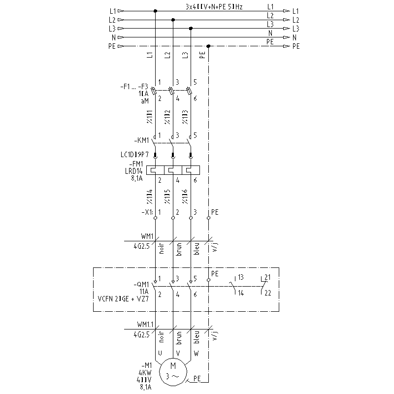
| Supply for motor version 2 |
| -Protection of the motor with fuse aM + contactor equiped with a thermal relay + load-switch for isolating |
| -Load-switch QM1 placed near the motor for isolating electrically when some revision work has to be done. Note the auxiliary contacts 13-14 and 21-22 which have to be wired in the control circuitry of the motor. |
| |
|
| |
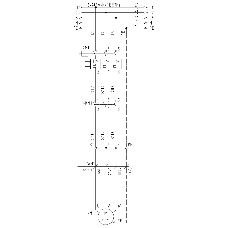
| Supply for motor version 3 |
| -Protection of the motor with a magnetical circuit breaker + contactor equiped with a thermal relay |
| |
| |
|
| |
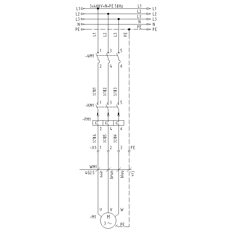
| Supply for motor version 4 |
| -Protection of the motor with a magneto-thermical circuit breaker + contactor |
| |
| |
|
| |
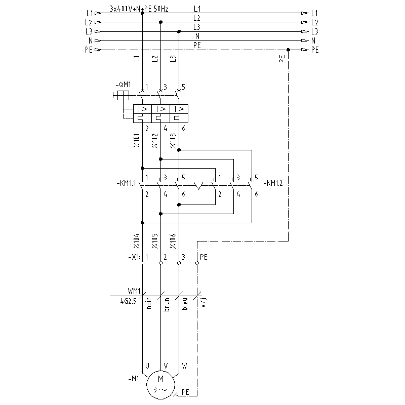
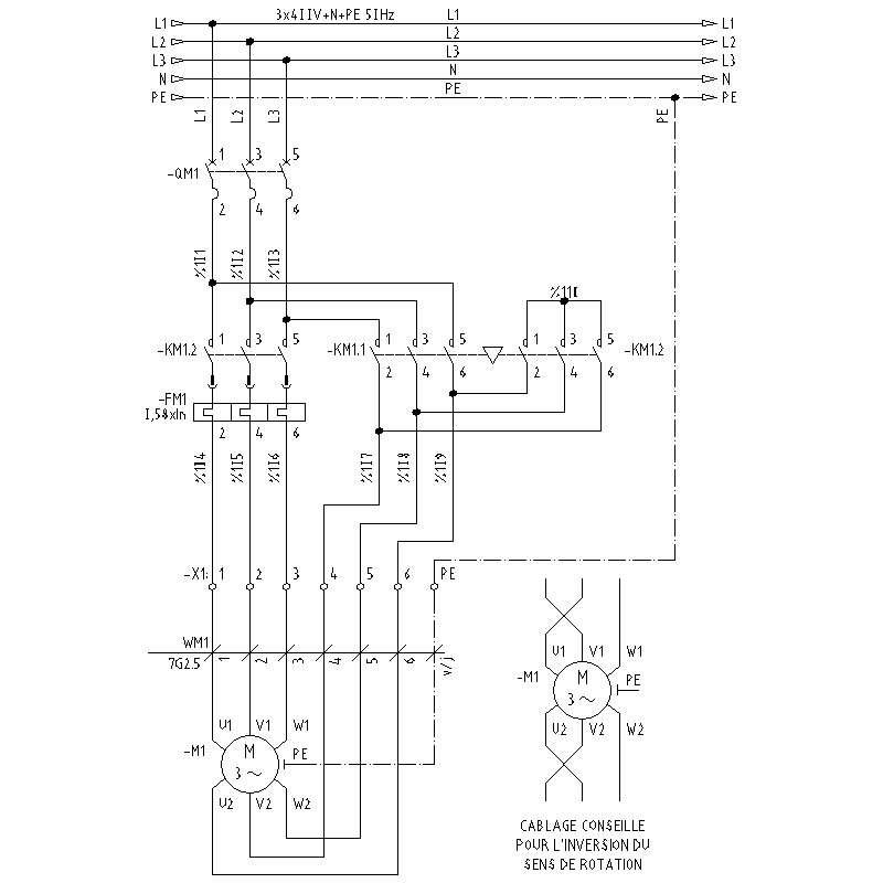
| Supply for motor version 5 (inverting of the rotating sens of the motor) |
| -Protection of the motor with a magneto-thermical circuit breaker + 2 contactors interlocked mechanicaly for inverting the rotating sens of the motor |
| |
| |
|
| |
| Star-Delta starting version 1 |
| -Protection of the motor with a magnetical circuit breaker + contactor equiped with a thermal relay (setting on 0,58xIn) |
| -See the detailed wiring of the motor if the rotating sens has to be inverted. |
| |
|
| |
| Normal-Emergency supply switching version 1 |
| -Control of the voltage on the Normal supply and switching on Emergency automatically in case of losing the Normal supply. |
| -Priority to the Normal supply |
| -Auto switching on the Emergency supply without additional control on the Emergency supply. |
| |

| Working detail of the switching |
| The relay K1 control the presence, the lose of phase , min or max voltage on the Normal supply circuitry. In belgium, we use frequently the relay V661 from the company AUTOMATION, but you can find equivalent type on the market. |
| When K1 detect a fault on the Normal supply, it is deenergised and break the supply of the relay K2T. |
| The contacts 13-14 and 33-34 of this relay let fall the coil of the contactor KM1 (Normal net), whereas the contacts 21-22 let the coil of the contactor KM1S be energised. The 2 contactors KM1 and KM1S are mechanicaly interlocked and also electricaly with the auxiliary contact 21-22. |
| To prevent that this system goes on and off without ending with a too fast switching, the relay K1 has to be set with a sufficent hysteresis time. |
| If the relay K1 doesn't have the possibility of setting an hysteresis time, we have to include a time-relay in the circuitry of the relay K2T |
| |
|
|
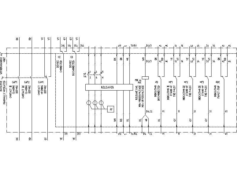
| Circuit-breaker withdrawable manually and equipped with : |
| -releaser STR |
| -release coil uppervoltage or undervoltage |
| -contact OF (1-2-3) indicating the position |
| -contact SD indicating fault-trip |
| |
| |
 |
| |
|
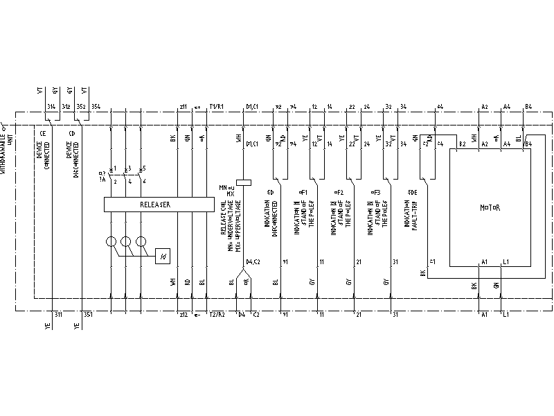
| Circuit-breaker withdrawable and motorised |
| |
| |
 |
| |
|
| 1. Sample of drawings (10.5Mb) |
| 2. Overview of the drawings : zip version (1.5Mb) or dwg version (8Mb) for printing these pages, is it better to make a script for the 63 folios of the drawing. Here you have the script that I use, compatible with Autocad 2005. Yet a remark : the English version is under the ENGLISH Layer (hard to find isn't it !). The two others languages have to be off, it is FRANCAIS and NEDERLANDS. |
| |
|
|