|
|
 |
|
|
|
Memento - 1 Generalities |
| |
| Standard paper format |
| Color code designation |
| Protection grade IPxx |
| Circuit-breaker curve |
| Security category |
| Designation of electrical material |
| |
| Standard paper format |
Paper format Serie 'A' |
Value in mm |
A0 |
841 x 1189 |
A1 |
594 x 841 |
A2 |
420 x 594 |
A3 |
297 x 420 |
A4 |
210 x 297 |
A5 |
148 x 210 |
| Color code designation |
| Black |
BK |
|
Grey |
G7 |
| Brown |
BN |
White |
WH |
| Red |
RD |
Rose |
PK |
| Orange |
OG |
Gold |
GD |
| Yellow |
YE |
Turquoise |
TQ |
| Green |
GN |
Silver |
SR |
| Blue |
BU |
Green-Yellow |
GNYE |
| Violet |
VT |
|
|
| Protection grade IPxx1 X2 X3 |
| Protection against dust |
|
Protection against liquid |
|
Protection level against mechanical shock |
| X1 |
|
X2 |
|
X3 |
Hammer weight [kg] |
Height of fall [m] |
Energy of the shock [J] |
| 0 |
no protection |
0 |
no protection |
0,5 |
0.15 |
0.1 |
0.2 |
| 1 |
protection against solid body > 50mm |
1 |
protection against dripping water |
1 |
0.15 |
0.15 |
0.3 |
| 2 |
protection against finger contact and to solid body > 12mm |
2 |
protection against dripping water (when tilted to 15° N) |
1,5 |
0.15 |
0.2 |
0.4 |
| 3 |
protection against tools contact and to solid body > 2,5mm |
3 |
protection against spraying water (when tilted to 60° N) |
2 |
0.15 |
0.25 |
0.5 |
| 4 |
protection against thin tools contacts and to solid body > 1mm |
4 |
protection against spraying water (in any direction 360°) |
3 |
0.25 |
0.2 |
0.6 |
| 5 |
full protection against contact and the deposit of dust |
5 |
protection against water jet |
4 |
0.5 |
0.2 |
1 |
| 6 |
dust tight |
6 |
protection againgst heavy seas |
5 |
0.5 |
0.4 |
2 |
| |
|
7 |
immersion |
6 |
1.5 |
0.27 |
4 |
| |
|
8 |
complete protection against submersion |
7 |
1.5 |
0.4 |
6 |
| |
|
|
|
8 |
5 |
0.2 |
10 |
| |
|
|
|
9 |
5 |
0.4 |
20 |
| |
|
|
|
10 |
15 |
0.235 |
35 |
| |
|
|
|
11 |
15 |
0.4 |
60 |
| Tripping curve of circuit-breakers |
Tripping curve type |
I short-circuit / I overload |
Use |
B |
3 ... 5 |
great length of cable |
C |
5 ... 10 |
standard use |
D |
10 ... 14 |
motors, transfos |
MA |
12 without overload |
for the motors, with overload relay combined to the contactor |
K |
10 ... 14 |
|
| Z |
2.4 ... 3.6 |
electronic |
| U |
5.5 ... 8.8 |
tertiary sector, industry, farming |
L |
2.6 ... 3.85 |
great length of cable |
Security category standard EN 954-1 |
| Category |
Brief description of the rules |
Behavior of the system |
Principle |
| B (basic) |
The safety-related parts of machine control systems and/or their safety devices and components shall be designed, constructed, selected, assembled and combined in accordance with the relevant standards so that they can withstand the expected influences |
A fault can lead to a lack of security function |
Largely characterised by the selected devices |
| 1 |
Same as B + use of principles and certified security devices |
Same behavior as B, but with a better reliability |
| 2 |
Safety-related parts of control systems must be designed so that their safety function(s) are checked at suitable intervals by the machine control system. The safety function(s) must be checked:
(a) at the machine start-up and prior to the initiation of any hazardous situation, and (b) periodically during operation, if the risk assessment and the kind of operation show that it is necessary
This check may be initiated automatically or manually. Automatically, for example, the check may be initiated by a signal generated from a control system at suitable intervals. The automatic test should be provided by preference. The decision about the type of test depends on the risk assessment and the judgement of the end user or machine builder.
The result of the test shall allow operation if no fault has been detected, or shall generate an output to initiate an appropriate control action if a fault has been detected. This requires a second, independent shutdown route
Notes:
In some cases Category 2 is not applicable because the checking of the safety function cannot be applied to all components and devices. Moreover, the cost involved in implementing Category 2 correctly may be considerable, so that it may make better economic sense to implement a different category.
In general Category 2 can be realised with electronic techniques. The system behaviour allows that: the occurrence of a fault can lead to the loss of the safety function between checks; the loss of the safety function is detected by the check. |
A fault is not recognised until the peridic safety check is not done |
Largely characterised by the structure of the control |
| 3 |
Safety-related parts of control systems must be designed so that a single fault in any of these parts does not lead to the loss of the safety function. Whenever reasonably practicable, the single fault shall be detected at or before the next demand upon the safety function.
This does not mean that all faults will be detected. The accumulation of undetected faults can lead to an unintended output signal and a hazardous situation at the machine. |
The safety function is maintained with the loss of a single fault |
| 4 |
Safety-related parts of control systems must be designed so that a single fault in any of these parts does not lead to a loss of the safety function; the single fault must be detected at or before the next demand upon the safety functions (e.g. immediately at switch on, at the end of a machine operating cycle). If this detection is not possible, then an accumulation of faults shall not lead to a loss of the safety function. |
The safety function is maintained, even with the accumulation of faults |
| It is to the customer to specify the security category complying with EN 954-1 for specialised systems |
Safety risk analysis must be complying with EN 1050 or EN 292-1. The contracting party configure the application on basis of these security rules.
|
|
|
|
|
Designation of electrical material |
| The designating code appear at a suitable place near the symbol. It establish a relation between the considered material in the equipment and the documents (schematics, bill of material, developped schematics, instructions). For the ease of the maintenance, it can be brought in full or partially on the material or in the proximity.
The designation of electrical material is done by blocks identified by symbols, these last serving to differentiate the blocks 1,2,3,4. |
| Block 1 |
Upper function from where come all relation with other parts of the installation locally or in the behavior. |
| Block 2 |
implanting of the material |
| Block 3 |
identification of the material |
| Block 4 |
designation of terminal and wires |
|
| = |
1 |
+ |
2 |
- |
3A |
3B |
3C |
: |
4 |
| |
Upper function (equipment) |
|
location |
|
type |
sequence order |
function |
|
connexion |
|
| |
| |
| The following types are prefered |
| 3A-3B-3C or |
| 3A-3B or |
| 3B-3C |
| |
| Letters for the block 3A - From now on the text has to be translated (be patient) |
| The following table show the characteristic letters for the materials. Beside the letter determining the type of material, we can use the letters determinig its use so that the designation reinforce the identification of the device.
|
| A |
Assembly,
Sub-functionnal-assembly. |
Combination of device making an unit; from construction but that it is not possible to classify with another letter
Tube amplifyer or with transistor, magnetic amplifyer, laser, maser.
Electric Variator.
Programmable Logic Controler (PLC). |
| B |
Converter of non electric value in electric and inversely |
Converter of pressure measure, quantity, temperature, speed, level. Proximity detector. Thermocouple, fotoelectric cel, electrical dynamometer, transducer with cristal, microfone, reading head, synchro-transmetteur. |
| C |
Condensator |
|
| D |
Binary element
Time delay device
Memory device |
Devices and integrated circuits of binary equipment and digital command, regulation and calculus. Monostable bridge or bistable, magnetic memory, recorder on tape or on disk. |
| E |
Miscellaneous |
Devices not included here such as the lighting and heating devices |
| F |
Protection device |
Circuit-breaker, fuse, protection relay, manostat, overvoltage limitator, lightning protector |
| G |
Generator, supply device |
Generator, alternator, converter, supply box, charger, battery, oscillator, oscillator with quartz |
| H |
Indicator device |
Optical and accoustical signaling device |
| J |
|
Free |
| K |
Contactor, relay |
Power contactor, auxiliary contactor, timedelay relay, auxiliary relay |
| L |
Coil |
Transducer, induction coil, blocking coil |
| M |
Motor |
|
| N |
Amplifyer, regulator |
Device for command equipment, for regulation and for analog calculus |
| P |
Measuring device, Control device |
Measuring device, indicator and recorder, counter, hour commutator |
| Q |
Cutting device for strong current |
Circuit-breaker, loadswitch, motor circuit-breaker |
| R |
Resistance |
Adjustable resistance, potentiometer, rheostat, shunt, thermistance |
| S |
Control commutato |
Command auxiliary, push-buton, selection switch, end limit-switch, telefone dial wheel, connexion stage |
| T |
Transformer |
Current transformer, voltage transformer |
| U |
Modulator, converter of electric value |
Codification device, inverter, frequence discriminater, frequence converter, converter rectifier, autonome inverter |
| V |
Semi-conductor, tube |
Transistor, thyristor, diode, electronic tube |
| W |
Conductive |
Bus bar, wire, cable, wave guide, coupleur, directif wave guide coupleur, dipole, parabolic antenna |
| X |
Terminal, plug and socket |
Plug and socket connexion, clips, test plug, terminal plate |
| Y |
Mechanical device electrical actuated |
Brake, clutch, valve engine, pneumatic electrovalve |
| Z |
Filter, corrective, limitator |
RC or LC filter, device limitating the interference, smooth-out device, differentiel transformator, cristal filter |
|
| |
| Letters for the block 3C |
| A |
Auxiliary function, "OFF" function |
| B |
Direction of working |
| C |
Numerical counting |
| D |
Differenciation |
| E |
"ON" function |
| F |
Protection |
| G |
Controle |
| H |
Signaling |
| J |
Integration |
| K |
Use of push-button |
| L |
Wire location |
| M |
Main function |
| N |
Measure |
| P |
Proportional |
| Q |
Status (starting, stop, limitation) |
| R |
Reset, clearing |
| S |
Memorisation, storage |
| T |
Delaying, timing |
| U |
- |
| V |
Speed (acceleration, breaking) |
| W |
Summing |
| X |
Multiplication |
| Y |
Analog |
| Z |
Digital |
|
| |
|
Sample of identification |
| Full identification in which the essential subdivision indicate the location |
=R057+5A3-Q6:2 |
| Terminal 2 |
| of circuit-breaker 6 |
| from sub-assembly A3 |
| in assembly 5 |
| in the room 057 |
| |
| Identification in which the essential subdivision indicate the function of the element in the full equipment |
=3T7-M84 |
| Motor 84 |
| Pomp 3 of cooling of turbine 7 in assembly |
| |
| Identification for indication of type, of sequence number and of function |
-K3M |
| K=Contactor |
| 3=sequence number |
| M=main function |
|
| |
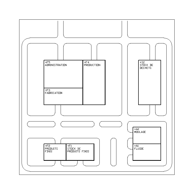
| Sample of a plant |
|
|
|
|
|
|
 |
|
|
|
|
|
|
| |
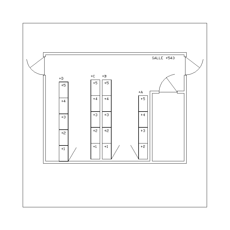
| Sample of installation plan |
|
|
|
|
|
|
 |
| |
| HOME |
|
|
|
|
|
|
|
|
|